Image
resonance imaging (MRI), Part 1 How it works
Slide 1 of 39. Slide 1 of 39
260 mri system block diagram [PPT Powerpoint]
Between the two, the key differences you need to be aware of are: T1 - ONE tissue is bright: fat. T2 - TWO tissues are bright: fat and water ( WW2 - W ater is W hite in T 2) T1 is the most 'anatomical' image (Figure 1). Conversely, the cerebrospinal fluid (CSF) is bright in T2 due to its' water content. T2 is generally the more.

Mri system block diagram
Magnetic resonance imaging (MRI) is a powerful diagnostic tool that can be optimized to display a wide range of clinical conditions. An MRI system consists of four major components: a main.

PPT My spin on MRI The basics of MRI physics and image formation
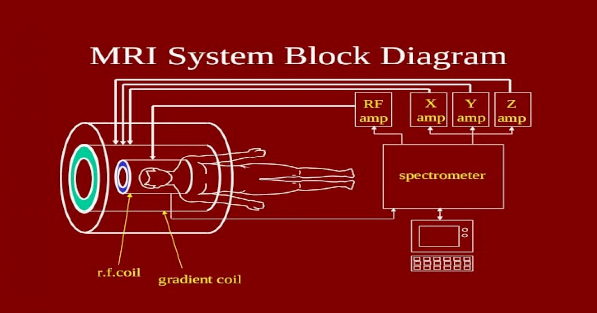
The block diagram in Fig.I-1 shows typical interaction pathways between the major sections of an MR imaging system (3). At the present time a wide range of magnetic field strengths is available. Table l-2 shows some typical magnetic field strengths available commercially, ranging from 0.02 Tesla to around 15 Tesla.

Mri system block diagram
Resultant magnetic field on the voxel. The longer the RF pulse is applied, and the stronger it is, the bigger the deflection of the net magnetic field, that is, the bigger the angle α. x-y plane. It can reach 90, or even 180 degrees. The bigger α, the longer it takes to recover when the RF is turned off.
Mri system block diagram
Blood oxygen level dependent (BOLD) MRI, also called functional MRI (fMRI), is one of the most widely used modalities for studying brain function.
The block diagram of the spectralscanning MRI (SSMRI) system and SSMRI
Slide 2 of 49. Slide 2 of 49

Mri system block diagram
Magnetic Resonance Imaging (MRI) is one way for healthcare professionals to look inside your body and see what is going on inside it without having to cut open your body.While there are lots of different ways to take pictures inside your body such as x-rays, computerized tomography (CT) scans, ultrasounds and so on, MRIs produce far more detailed images of the structure of a patient's blood.

MRI system components and their relationship. a, b Block diagram (a
Block diagram of an MRI imaging system. Static Magnetic Field MRI imaging requires the patient to be placed in a strong magnetic field in order to align the hydrogen nuclei. There are typically three methods to generate this field: fixed magnets, resistive magnets (current passing through a traditional coil of wire), and super-conducting magnets.

Block diagram of MRI compatible masterslave prostate biopsy
Slide 27 of 57. Slide 27 of 57

Patent US6289233 High speed tracking of interventional devices using
The block diagram of a typical MRI system with the components, pulse. | Download Scientific Diagram Figure 2 - uploaded by Richard Magin Content may be subject to copyright. The block.

How Resonance Imaging (MRI) Works Electrical and Electronics
Medical application - Magnetic Resonance Imaging (MRI) block diagram Posted on May 19, 2014 by Electronic Products Magnetic Resonance Imaging (MRI) helps us visualize the structures of the body that include water and fat molecules.

Image
Lucidchart's block diagram software is quick & easy to use. Get the most powerful, professional diagram software on the market.

Block diagram of MRI compatible masterslave prostate biopsy
Magnetic Resonance Imaging (MRI) is a non-invasive imaging technology that produces three dimensional detailed anatomical images. It is often used for disease detection, diagnosis, and treatment monitoring. It is based on sophisticated technology that excites and detects the change in the direction of the rotational axis of protons found in the water that makes up living tissues.

Schematic of the MRI system (Adapted from [18]) Download Scientific
View the TI MRI block diagram, product recommendations, reference designs and start designing.

Block diagram for an ISS Compact MRI system. Download Scientific Diagram
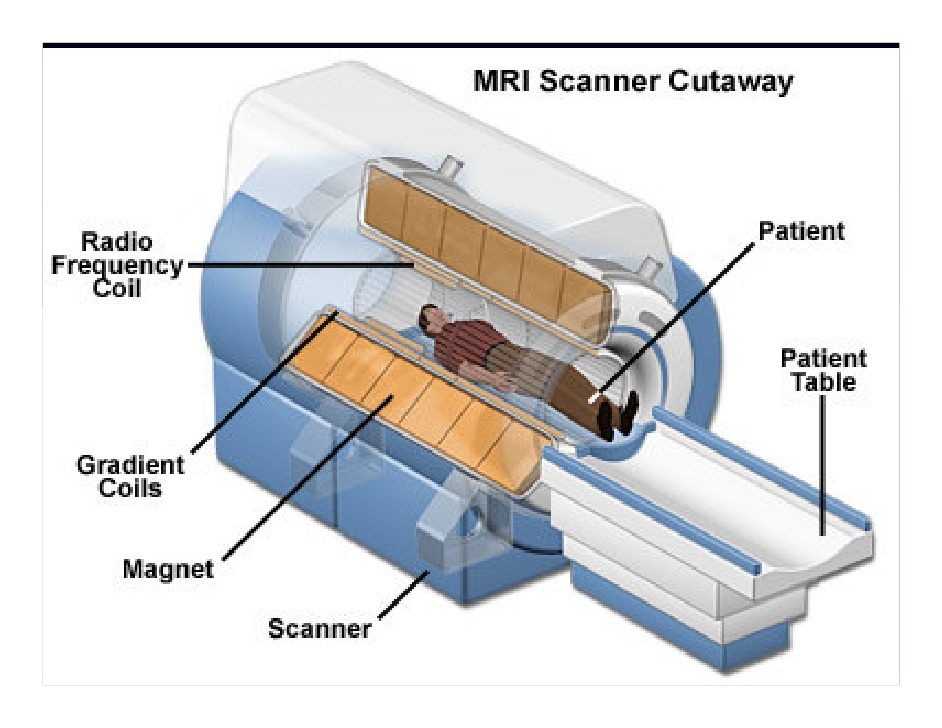
2.6 Imaging Hardware. An MRI scanner is made up of four components: the magnet, gradient coils, r.f. transmitter and receiver, and the computer. In this section the general design and construction of these components is discussed. More specific details of the system used for the experiments in this thesis are given in the relevant chapters.